Whether you have a novel material that you need to characterize or you want to further optimize a more common material, it’s critical to ensure that your print parameters result in a construct that fits your criteria. Before you follow this protocol, a good question to ask yourself is what are you optimizing for? Is it for strength? Speed? Cell viability? This article will walk you through the steps for proper print parameter optimization to ensure you have a successful experiment.
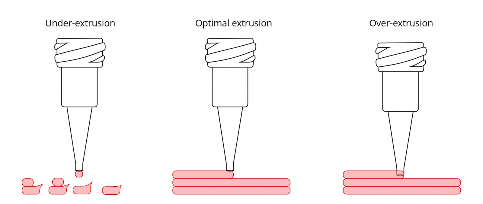
For clean and repeatable prints, you need to ensure that you have consistent extrusion of your material. Under-extrusion can lead to poor layer building while over-extrusion can lead to sloppy prints from dragging your needle through the material.
Results: This protocol will help you determine the material’s print pressure.
Figure 1
Fill a syringe with your material and load it into the Allevi.
In the Allevi software, press and hold the extrude button. Release to stop extruding.
If there was no extrusion or uneven extrusion, increase the pressure by 5 PSI.
Repeat steps 2 and 3 until the material extrudes evenly.
Repeat this process to get three pressures the material extrudes at, varying from a slow to fast extrusion.
Notes to consider:
How does temperature or additions like cells and ECM affect your material’s viscosity? What is the composition of the final bioink you plan on printing?
There are a variety of factors that can affect the pressure needed for extrusion. Take note of what needle gauge and shape you are using. To lower the pressure needed for extrusion, try using a lower gauge or a tapered needle. For more information on needles, check out our Guide to Picking Your Needle.
Material volume loaded into the syringe can also have an effect on pressure. Generally, material volume fluxes of ~ 2 ml can affect the pressure needed for extrusion.
Troubleshooting tips:
Each time you increase the pressure, be sure to first release the extrude button and allow the pressure to change.
Be aware of what temperature you are completing the extrusion test at. Many materials change viscosity when heated or cooled. If you needed to heat or cool the material before loading into the syringe, take note of the amount of time allowed to reach printing temperature for future tests. Allevi 1, 3 and 6 offer a wide range of printing temperatures: from 4 °C to 160 °C. Allevi 2 can heat up extruder up to 160 °C.
If the desired material takes a long time to cool or heat to desired print temperature, try placing the loaded syringe in an ice bath or heated water bath to speed the process.
Volume Test
A volume test allows for the estimation of volume extruded from the printer. By determining the density of the material, the mass of printed samples can be used to determine volume output as a function of time spent extruding. This will also be helpful if you plan on printing dots of a certain volume.
Results: This protocol will help you determine the material’s flow rate and density.
Figure 2: (a) Weight of 3 pipetted volumes (b) weight of extruded materialEquation 1
If you know your material’s density, skip these next 2 steps. Otherwise, to find the relationship between weight and volume:
Weigh a series of known volumes (pipetting usually works best) of the desired material. We recommend using at least 3 volumes.
Plot the weights of these measurements against volume and use a line of best fit to estimate weight increase by volume (see figure 2a). The slope of this line is the density.
To find the relationship between weight and extrusion time:
Load a syringe with your material into the Allevi at the temperature and pressure you plan to print. Flow rate is very dependent on your choice of needle and print pressure.
Using the code sample below, create 3 G-code files with different extrusion durations (edit the number after “S” in line 7).
G1 X0 Y0 Z25 ; Center the print head high at Z=25
T0 ; Activate first extruder

; Extrusion
G92 E0 ; "Zero" the pressure
G1 E0.1 ; Start extruding
G4 S1.0 ; Wait for 1 seconds "S{duration in seconds}"
G92 E0 ; Stop extruding
Print these G-codes and catch the extruded material using a weighing tray (the print head will extrude into midair).
Weigh the sample and graph results for all extrusion times (see Figure 2b). We recommend repeating this 3 times per extrusion duration.
Plot the results and use a line of best fit to determine the weight increase by extrusion time. The slope of this line is the mass flow rate.
To determine your volume flow rate in mL/s, multiply the inverse of your density by your mass flow rate!
Crosslinking Test
Many biomaterials are soft and may not hold their structure after being printed. In this case, it is necessary to crosslink them in order to build a construct with good shape fidelity. Biomaterials can be chemically-, thermally-, or photo- crosslinked.
Results: This protocol will help you determine the material’s crosslinking settings.
Equation 2
Extrude equal amounts of material into a well plate and crosslink at varying levels. This may involve different temperatures, different lengths of time, different chemical concentrations, or different light intensities depending on your material’s crosslinking mechanism.
Next, dry the samples in a vacuum oven overnight, then record the dry weight of each sample (w1).
Immerse the samples in a solution in which they would dissolve if not crosslinked.
Example: gelatin methacrylate should be immersed in PBS or deionized water and heated to 37 °C.
After 24 hours, remove the samples from solution and dry in a vacuum oven overnight. Record the weight of the dry samples (w2). Compare this second weight to the original weight to obtain the sol fraction (Equation 2).
A sol fraction of 100% correlates to a sample that has not crosslinked at all, while a sol fraction of 0% correlates to a sample that has completely crosslinked
Line Test
Once a range of pressures for extrusion has been determined, feed rate, path height, and print speed must be optimized. This can be completed through a line test in which various lines are extruded at different print speeds (Figure 1). A line test using G-code provided by Allevi should be completed for each pressure and needle to be tested. Once completed, the lines can be analyzed via brightfield microscopy for accuracy and precision.
Results: This protocol will help you determine the material’s print speed, layer height, and line resolution for a given pressure and needle.
Our pre-sliced G-code is written to make editing it easy. You can modify it in your preferred text editor. The G-code is set up in the section as shown below.
Determine 3 print speeds and 3 layer heights you want to test.
Note: Needle tip diameter is a good layer height to start with.
Download the Line Test G-code above. Open it in a G-code or text editor.
Edit the G-code to set layer heights.
Layer height remains the same across rows (A, B, C). Edit the layer heights for these rows by changing the Z value. You should only need to change 3 values. Lines 20, 60, and 101
Edit the G-code to set speeds.
Speeds remain the same across columns (1, 2, 3). Edit the speeds for these columns by changing the F value. You will need to edit the speed for each section (9 total).
Note: In G-code, speed is written in the unit of ‘mm/min’ rather than ‘mm/s’. This means that ‘mm/s’ speeds are multiplied by 60.
Save the file.
Load your material into a syringe, attach your desired needle, and set the pressure to your previously determined value.
Print your line test G-code file.
(Optional) Use brightfield imaging and an image analysis software (such as ImageJ) to determine resolution and variance.
Troubleshooting tips:
Start with a wide range of speeds and path heights, then test a narrower range to optimize.
If you find your line width is larger than desired, a smaller gauge may allow for finer extrusion. However, this might affect extrusion pressure.
Larger line widths than expected may also be caused by incorrect path heights, which can cause the material to smudge. Try increasing path height.
Z-stack Print Calibration
To further test and confirm path height, the print settings determined from the line test should be tested/confirmed through a Z-stack calibration. This print will determine whether your material can repeatably build upon itself layer-by-layer at your print settings. The accuracy of Z-direction can be determined by measuring the final height of the construct and comparing it to the height from the design file.
Results: This test will help you determine Z-resolution as well as check the layer height and crosslinking profile.
Go the Allevi Bioprint Online and connect to your printer.
In the Print File section, click ‘Add file’ and go to Allevi Files and select the 10mm cylinder.
Enter your layer height and print speed in the slicer settings. Leave the infill set to ‘None’.
Set your pressure, add any crosslinking settings.
Click print.
Compare the final height of your construct to the height of your 3D model. How does it stack up?
Troubleshooting tips:
Does your structure collapse during print? It may require additional crosslinking during the print in order to improve structural support.
If you are still having issues after increasing the crosslinking time of initial layers, you can also try enlarging the width of layers for increased support.
If the needle starts to run into previously printed layers, your path height is likely too small. Try increasing path height.
If the material extrudes only in droplets as layers increase or if there are gaps in your structure, either the path height is too large or the print speed is too high. Try either decreasing path height or decreasing print speed. You may need to revisit the Extrusion Test or Line Test.
This final calibration tests all optimized parameters from previous calibrations, as well as complexity in 3D dimensions. Print multi-layer lattices of varying sizes with previously determined print parameters. This calibration test is meant as a final step to confirm all previously optimized parameters. If this test is not optimized, you may need to return to previous steps to recalibrate certain print settings.
Results: This calibration step allows for the final testing of optimized print parameters.
X/Y Resolution Print Test (Optional)
Once pressure, gauge, path height, print speed, and feed rate are optimized and finalized, the material spatial resolution in x and y directions can be determined. This can be completed through a resolution test with the STL provided by Allevi.