Overview
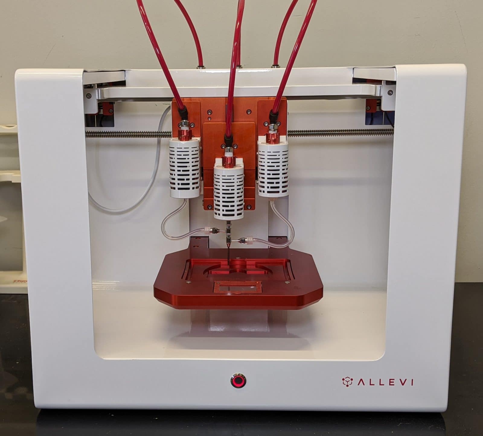
The Allevi Triaxial Kit allows users to mix materials from three syringes during printing. Triaxial bioprinting allows for a new level of complexity and during-print material mixing. This is especially useful with working with materials that require curing catalysts or liquid crosslinking agents. These materials may not be viscous enough to print without these agents or too viscous to be extrudable when mixed in the syringe.
Materials
- Triaxial nozzle
- Allevi triaxial tubing with luer lock connectors
- Syringe couplers (2)
- Allevi Plastic Syringes (PSYR5)
- Petri dish or Microplate
- Desired bioinks/materials
- Recommended: Pluronic, Alginate, Calcium Chloride, Silicone, etc
- NOTE: Thermoplastics are NOT compatible with the triaxial nozzle
Methods

Notes:
- Do not print at temperatures above 40C using the triaxial nozzle.
- Do not print at pressures above 90 PSI using the triaxial nozzle.
- Do not autocalibrate the triaxial nozzle.
Setup
- Attach all print heads to the printer.
- Place syringe with Material A into Extruder 1.
- Place syringe with Material B into Extruder 2.
- Note: we have found that attaching the triaxial nozzle directly to the syringe containing the most viscous material yields better printing results.
- Place syringe with Material C into Extruder 3.
- With the bed plate all the way down, attach the triaxial nozzle to the syringe in Extruder 2.
- Attach syringe couplers to side syringes in Extruders 1 and 3.
- Attach the tubing from side Extruders 1 and 3 to the triaxial nozzle side ports.
- Use the Allevi Bioprint Online software to adjust the temperature and pressure on each extruder, then test extrusion with a secondary container to catch any extruded material.
- Prime the nozzles: ensure materials A and C in the side extruders have travelled through the tubing and are within the triaxial nozzle.
- Note: depending on individual nozzle gauge it may be difficult to extrude higher viscosity bioinks through certain side ports.
- Manually calibrate the nozzle (Extruder 2).
- DO NOT AUTOCALIBRATE.
- Move Extruder 2 into the down position.
- Manually position Extruder 2 with the nozzle lightly touching the center of the build plate and click “Set Calibration”.
- Switch to Extruder 1 in the software and click “Set Calibration” Do not move the nozzle. Repeat for Extruder 3.
- Switch back to the Extruder 2 tab.
- Upload your modified G-code.
- Click print and watch it go!
G-code
- Slice your desired STL file with settings for one extruder.
- Note: remember that
T0codes for extruder 1 (left when facing the printer),T1codes for extruder 2 (middle when facing the printer), andT2codes for extruder 3 (right when facing the printer). - You can follow the slicing steps described in our Bioprint Online Guide, making sure to designate Extruder 2 for any and all files.
- Note: remember that
- The line of code to turn pressure on is
M106andM107to turn it off;- Example:
M106 T0turns Extruder 1 on. - Note: For extruder 2, change
T0toT1. For extruder 3, changeT0toT2.
- Example:
- Insert the on-command for your first desired extruder after the first
G1 X_ Y_ E_command. - Insert the off-commands for the remaining extruders. In our case we would add
M107 T1andM107 T2. - Finally, insert the off-commands for all extruders after every
G92 E0command to ensure that no extrusion occurs during movement.
Example code
This G-code snippet prints a 0.6 mm tall, hollow cylinder with 0.2 mm walls. The first step to transform this code (or any G-code) into a triaxial code is to copy it into your preferred text editor, so that you can more easily edit your code.
- NOTE: The above G-code is NOT a triaxial G-code. It is for practice in this example. The final G-code is available below
In the editor, paste M107 commands to turn off all extrusion after the G92 E0 at the very beginning of the G-code file (line 5). If extruders need to be activated after a layer move, please see troubleshooting note 4. Then, find the line of code that tells your extruder to move into the first printing position. That line is typically formatted like so: G1 X_ Y_ E_. In our example, the first line that contains this type of code is now on line 13. Right below that, add M106 T0 to turn on extruder 1, M106 T1 (for extruder 2), or M106 T2 (for extruder 3). Make sure to add off-commands for the remaining extruders or they may also turn on. The new code will look like the following:
5  G92 E0
6  M107 T0
7  M107 T1
8  M107 T2
9  G1 Z0.200 F240.000
10 G1 X-4.094 Y6.147
11 G1 X-4.479 Y5.891 E0.00206
12 M106 T0
13 M107 T1
14 M107 T2
15 G1 X-5.089 Y5.372 E0.00561
Now that you have your extruder 1 on-command, let’s switch it off before moving to the next layer. Search for the next G92 E0 command. In this case, it is now line 73 (since we added 6 lines to the entire code). Add your off-command lines to turn off all extruders after this. It will look like the following:
71 G1 X-3.756 Y6.372 E0.20473
72 G1 X-4.069 Y6.164 E0.20640
73 G92 E0
74 M107 T0
75 M107 T1
76 M107 T2
77 G1 Z0.400
78 G1 X-4.094 Y6.147
This G-code will turn on extruder 1 at the beginning of the print and turn it off after the first layer has been printed. Now edit in on- and off- commands so that the other two extruders print the remaining two layers. The final code will look like the following:

Cleaning the triaxial nozzle

- Unscrew the nozzles by holding the hub where indicated above (A) and turning the inner hub counter-clockwise (B). The middle nozzle hub (A) can be removed from the outer nozzle (C) in the same manner.
- Note: be careful not to apply force to the inlets, this can cause the stem to disconnect. If the nozzle is too difficult to loosen, please contact [email protected].
- Soak in water for 10-15 minutes or overnight.
- Adding soap can help loosen material.
- Perfuse individual nozzles and tubing with water to clear any remaining material.
- Reassemble nozzle and perfuse with water again.
Troubleshooting/Pain points
- When attaching the plastic luer locks to the metal quick connects make sure to push on the luer lock while twisting so the threading catches. It is possible to strip the plastic threading.
- When the nozzle is assembled tightening or loosening the individual parts slightly will cause the nozzle tip of that individual nozzle to extend or retract. This offset of nozzle faces could change print properties slightly.
- Be sure to select the first extruder to be used in the software when the print is initiated. For example, if extruder 2 is the first to extrude during the print, make sure extruder 2 is selected in the software before pressing the “print” button.
- Extrusion during layer switch (Z movement) must include an ‘E-value’ in order to extrude.