Welcome to the Allevi Bioprint Online user guide! This guide will walk you through the details of each section of the Allevi software. You can also follow the steps in Getting Started for your first bioprint.

When you first login to Bioprint Online, you start at your Printer List. It shows you the printers registered to your account, each printer’s model, their serial numbers, their names, and their connection statuses.

This area lets you toggle between the Printer List and the Project workflow (Bioprint Pro). The Project workflow includes an object creator, a print visualizer, and material parameter recommendations. You can learn more about projects in our Printing with Bioprint Pro guide.

This area shows your current user profile and has a widget for our support chat service, Intercom. Intercom is the best way to get in touch with the Support Team for quick questions.

The connection status section shows the strength of the printer’s internet connection.

This button will disconnect you from the current printer. You will return to the Printer List, and the printer will no longer have you as an active user. Note that multiple users can connect to a single printer as long as the printer’s administrator grants them access.

You can use these icons to jump between the different sections of the software. The icon representing the section you are currently viewing will be highlighted in white.
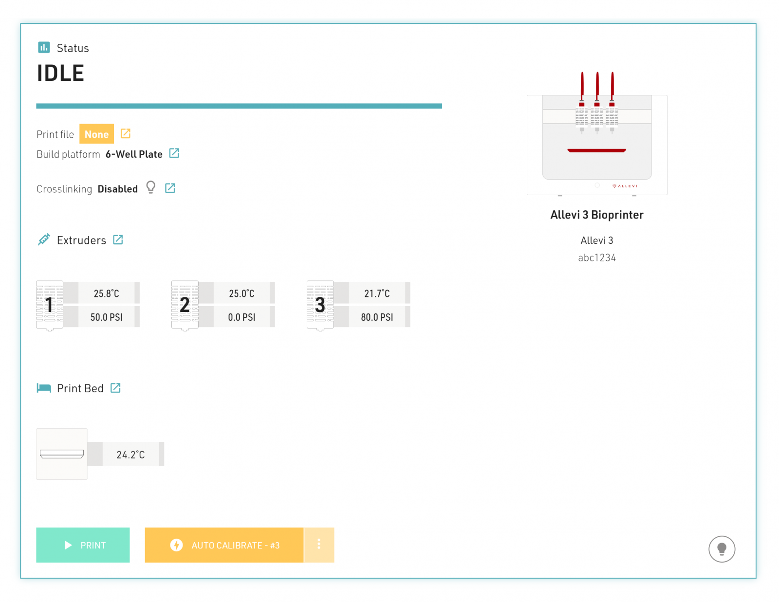


This section lists the name, printer type, and serial number of the current printer.

The Extruders section gives you a quick glance at the status of all the print heads.

This section will show the temperature of the bed plate.

This button will start a print! It cannot be pressed until a print file is selected and all attached print heads are calibrated.

Allevi 1 and Allevi 3 bioprinters have the autocalibration feature. The main autocalibration button will launch autocalibration for the first connected CORE print head. The three dot button can launch an “Autocalibrate All” function.

This button will toggle on and off the white lights of your printer. This can be helpful when manually calibrating or taking a video of your print. Additionally, if you ever get an error light, use this button to toggle it off.
Note: Allevi 2 users have a button that turns the extruder motor off in case of excessive noise. This button is not an emergency stop, if you need an emergency stop use the power button on the front of the printer.


This bar becomes visible at the bottom of the screen while viewing other sections of the software. It shows the current status of the printer and has a convenient print button, calibration button, and state light button.

This button will launch the file selection window. If you are using an STL file, you can continue clicking this button and adding more STL files to the build volume. If you are using a G-code, you cannot add more structures as the print path is already set. Therefore, the Add Print File Button will be unavailable unless you delete the current G-code in order to select a different one.
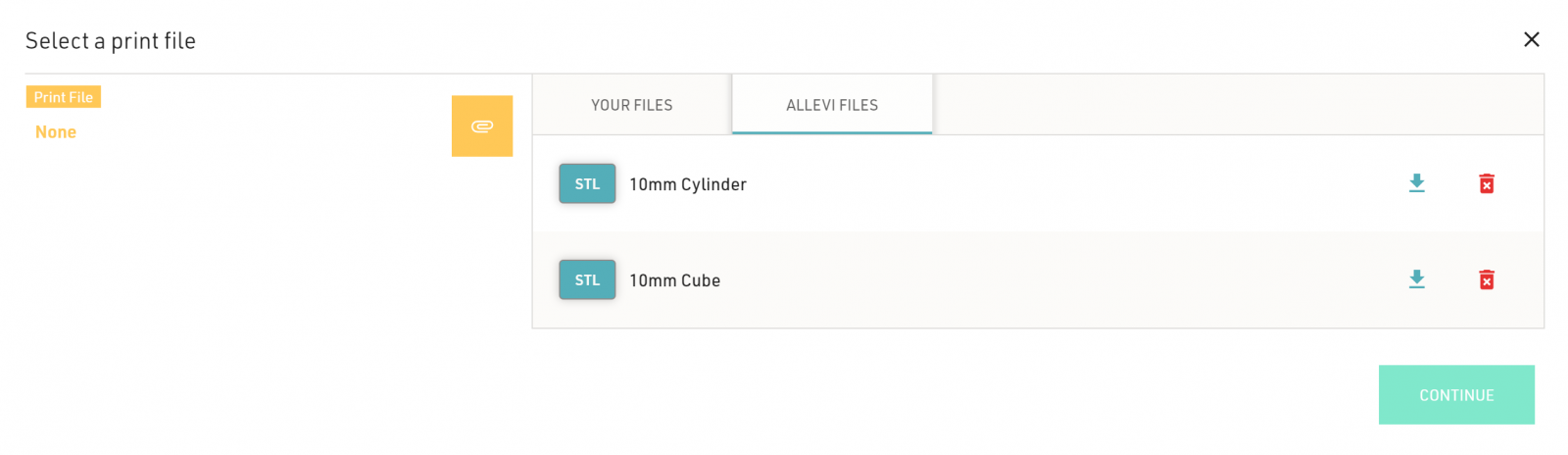
The Allevi Files tab has two STL files which are ready to start working with as soon as you start up your printer. The Your Files tab will show recent files that have been uploaded to your printer. To add more, click the yellow paperclip icon. In both tabs, files have an icon indicating their type (STL or G-code), a download icon, and a delete icon. Downloading a file is not necessary for printing, but it can come in handy if you want to save or edit files. The continue button adds the selected file as the print file and brings you back to the rest of the user interface.
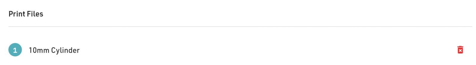
This section shows all of the files you have loaded into the software.

The general settings are required for both G-code and STL files. You can find general starter settings for different materials in our Print Parameters Cheat Sheet. Travel (non-printing) speed is automatically set to a max speed.

If you upload an STL file, you will have the option to add infill settings. G-codes do not offer this since their paths are already set.

If you are using an STL file, you can change the printing location within the build plate with the offset settings. Since most cell culture dishes are circular (petri dish, individual wells, etc), the Allevi software defaults to centering the STL file on the calibrated (0,0,0) point.
If you wanted to arrange multiple STL files to fit several in the build surface, you could use the X and Y offsets to do so. Similarly, if you wanted to make room for a thin base layer, you could adjust the Z offset. Note that relative to the calibrated (0,0,0) point, positive X coordinates are to the right, positive Y coordinates are toward the back of the printer, and positive Z coordinates correspond to a lower build plate (therefore more distance between the extruder and the build surface).

This button will create and download a G-code file of the current build volume design. While this is not required for printing, it can be convenient. For example, say you had 4 STL files in your build volume which all had different, specific infill settings and offsets. You could download the G-code version of your design and simply upload that G-code for future prints rather than editing all those settings every time.
Welcome to Allevi Bioprint Online! This guide will walk you through your Allevi bioprint online build plate section.
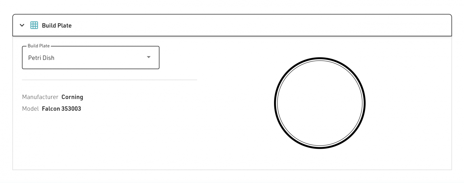

This drop-down menu lets you choose between the approved build plates.
This list will show the build plates available for your printer. If you don’t have access to one of the listed plates you can substitute a similar plate and manually calibrate. When substituting, make sure to match the number of wells on your plate with one of the plates on the list.
Important Note: The Allevi Software will reproduce the construct from the Current Print section in each of the wells of a multi-well plate. For example, if you wanted to work with a 96-well plate, you would only need to design the construct for the first well, rather than 96 individual constructs.

This section shows the manufacturer name and model number for the selected build plate. Different build plates have different dimensions which can interfere with the autocalibration and bioprinting process. It’s best practice to use the same model as shown. If you plan on always using a different dish, check out our article on resetting autocalibration.
The Extruders section is where you control important settings such as positioning, temperature, and pressure.
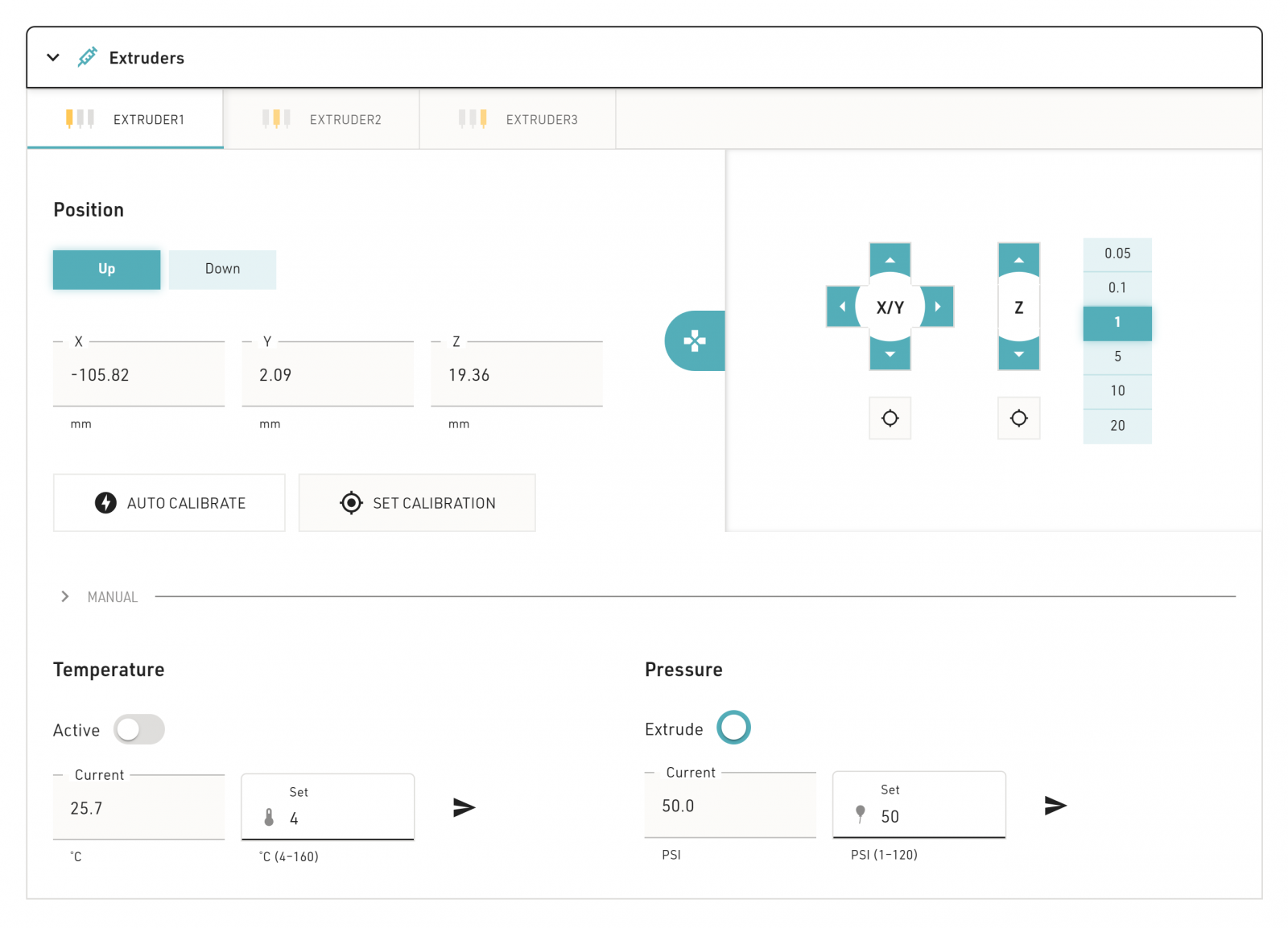
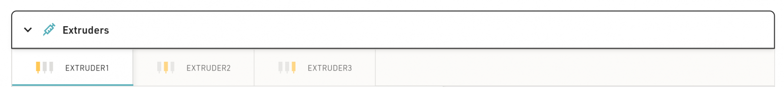
The extruder tabs let you pick between the different extruders on your printer to modify their settings. Make sure that you are on the right tab when changing settings! This tab also affects the settings in the Crosslinking section.

Allevi 2 and Allevi 3 users have multiple extruders they can use. They can use the ‘Down’ button to lower an extruder into the printing position. They can then use the ‘Up’ button to raise an extruder back into the neutral position.
The current position readings indicate the position of the tip on the given extruder. Hitting the manual calibration button will set these positions to 0 in all axes.

The small four pronged icon on the right side of the page opens the jog panel. The scale on the right side of the jog panel are set the step size (in millimeters). The X/Y arrow buttons move the extruder in the X/Y plane. The Z arrow buttons raise and lower the bed plate, respectively. The 

Allevi 1 and Allevi 3 users have the option to launch an autocalibration of the given extruder from the extruder section. Such autocalibrations follow the same process as those launched in the status section and the status bar. All printers will have a ‘Set Calibration’ button used to perform a manual calibration here as well. Clicking the ‘Set Calibration’ button will overwrite any previous calibration for the given extruder. The current position readings will also go to (0,0,0).

The manual position settings are found under the ‘Manual’ tab in the ‘Position’ settings. If you want to move the extruder to a specific position, you can enter the desired coordinates in their respective fields and send the command. This is often faster than using multiple clicks in the jogging panel.

The ‘Current’ window displays the temperature in the syringe channel of the given extruder. This is spatially as close to reading the temperature in the syringe as possible. If you want to use the active temperature control, enter the desired temperature in the ‘Set’ window and hit the send button. The ‘Active’ switch will move to active when you hit send. The switch also toggles temperature control on and off.

The ‘Current’ window shows the pressure currently supplied to the given extruder by the printer’s pneumatic system. To modify the pressure sent to the given extruder, enter the desired pressure in PSI to the ‘Set’ window and click the send button.
Important: Ensure that your air compressor is supplying more air pressure to the printer than you are requesting at the extruder! The printer can manage excess pressure from the source, but it cannot compensate for insufficient input. If your extruder cannot reach the target pressure due to an inadequate supply, your printer will stop active pressure control and turn on a red error light.
Pressing and holding the ‘Extrude’ button will exert the current pressure value in the given extruder to the inserted syringe. This is useful for clearing an obstruction, priming a new syringe tip, or testing your print parameters.
Photocrosslinking is a common method for stiffening or crosslinking hydrogels in bioprinting. One of the CORE print head’s highlights, available on the Allevi 1 and Allevi 3, is having both UV (365nm) and Blue (405nm) light crosslinking. There are three easy-to-use settings available in the Allevi software. If you do not need to use crosslinking, you can leave the settings as disabled. The settings here are assigned to whichever extruder is selected in the Extruder section.
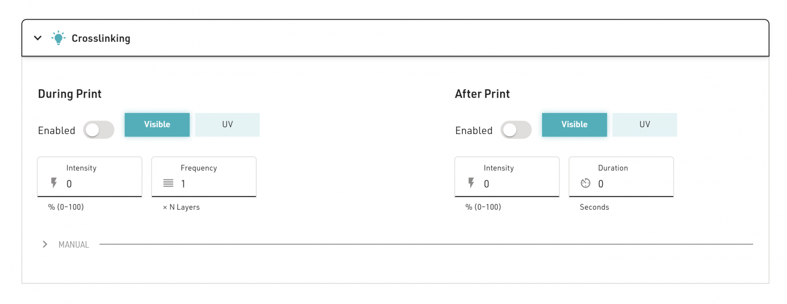
When building tall structures from photocrosslinkable materials, you often need to crosslink many times during the print. Crosslinking after every layer (N=1) or every other layer (N=2) are common choices. When enabled, the print head will center your LED of choice over your construct and crosslink it at the set Intensity for the set Duration at the set Frequency, then resume printing.
Note: A previous version of the software turned on the crosslinking light while the layer was being extruded. To avoid uneven crosslinking of extruded material, it was revised to the above method. To keep using this previous method, enabled During Print crosslinking and leave the Duration as 0.
You can increase stability by crosslinking the completed construct further. When enabled, the print head will center your LED of choice over your construct and crosslink it at the set Intensity for the set Duration.
Note: If you are printing in a multi-wellplate, the printer will perform the After Print crosslinking for each well.
There may be times when you just want to turn on crosslinking. When active, the print head will turn on the LED of choice at the set Intensity wherever the print head currently is.
This section is only available for Allevi 3’s.
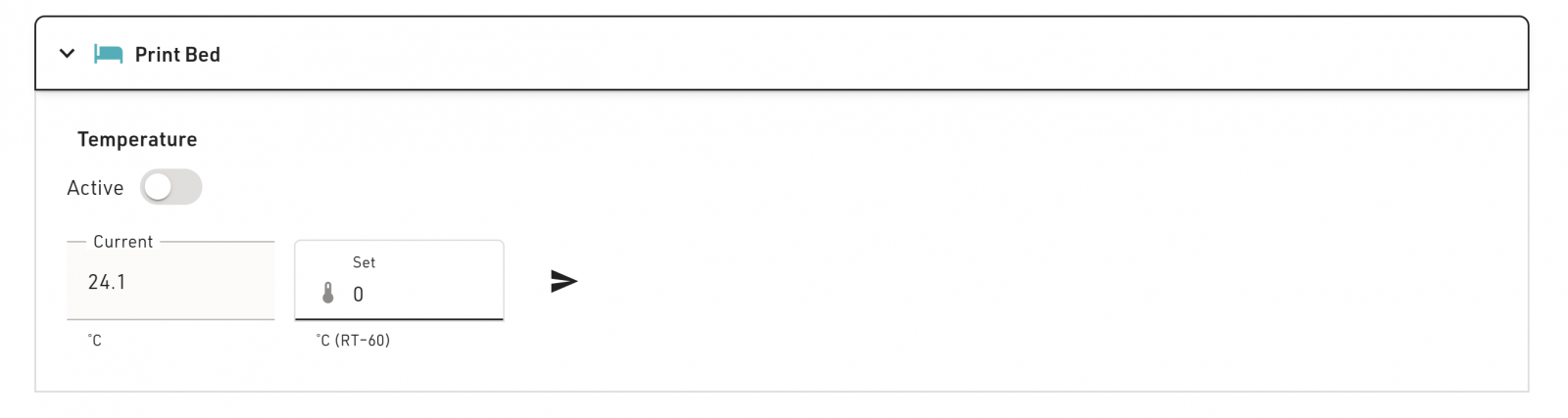
Allevi 3 users have access to a heated bed plate. The ‘Current’ window displays the temperature of the plate. To activate temperature control, enter the desired temperature in the ‘Set’ window and hit the send button. The ‘Active’ switch will toggle on when you hit send. Clicking on the switch also toggles temperature control on and off.
In order to ensure even heating across the bed plate, use the metal inserts included with the printer in your starter kit. The rectangular insert is good for petri dishes while the circular insert is for wellplates.
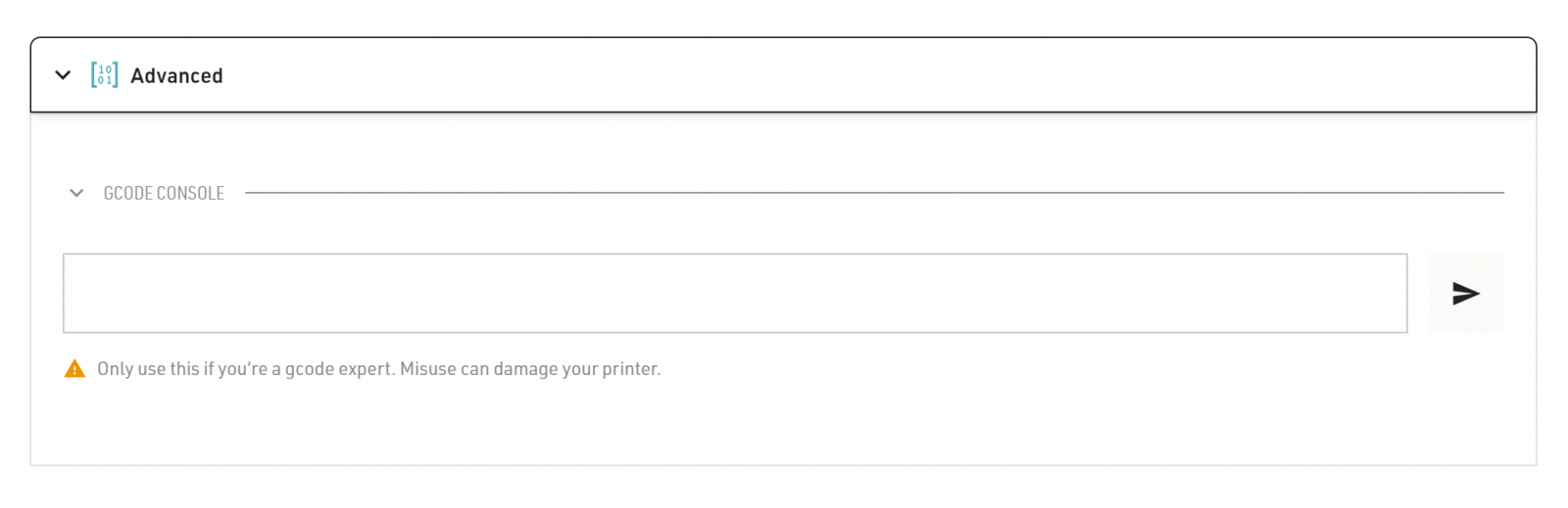
The advanced section features a G-code console. You can use this console to directly send G-code commands to the printer. However, there are no safety features in the console. Therefore, we recommend only using the Advanced section if you are a G-code expert or if you are troubleshooting with the Allevi Support Team.
If you have any questions or would like to schedule a call, please email the Allevi Success Team at [email protected].