
Overview
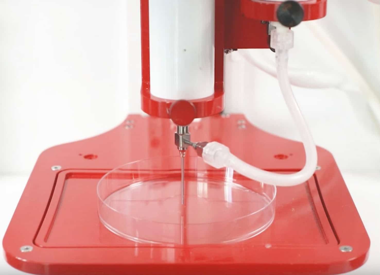
The Allevi Coaxial kit allows users with an Allevi 2 or Allevi 3 bioprinter to mix materials from two syringes during printing. This is especially useful when working with materials that require curing catalysts or liquid crosslinking agents. These materials might not be viscous enough to print without these agents or extrudable when mixed in the syringe. This protocol will walk you through a step-by-step process for coaxial bioprinting.
Some examples of materials that can be printed with the Allevi coaxial protocol are sodium alginate and calcium chloride, silicones, and their respective catalysts, or any other materials that you desire to mix during a print.
Materials
- Allevi coaxial nozzle
- Allevi coaxial tubing with luer-lock connectors
- Note: the coaxial nozzle is made of stainless steel and can be cleaned and autoclaved between uses. For new tubing, sterile Coaxial Kit refills can be purchased on the Allevi shop.
- Syringe coupler
- Allevi syringes
- Desired bioinks/materials (Alginate, Calcium Chloride, PDMS, Silicone)
Methods for Coaxial Bioprinting:
Setup
- Insert your loaded syringes in adjacent Allevi extruders;
- Attach the coaxial nozzle to one syringe;
- Note: we have found that attaching the coaxial nozzle to the syringe containing the most viscous material yields better printing results.
- Attach the tube luer-lock to the coaxial nozzle;
- Attach the remaining tube luer-lock to the syringe coupler;
- Connect the syringe coupler to the other syringe;
- Note: it might be helpful to not have the tubing connected to your syringe for this part. That way, the syringe can rotate during attachment without disturbing your setup.
- Attach all printer tubing to the syringes;
- Home all axes to make sure your tube placement is not affecting extruder movement;
- Note: if the tubing is in the way, re-adjust and retry homing.
- Calibrate your extruder nozzle manually and set up your print choosing the desired pressures for each syringe. Make sure to test which pressures are optimal for your materials.
- Note: when optimizing print parameters start with low pressures and slowly increase until consistent material extrusion is maintained to avoid detachment of the coaxial tubing.
- Note: make sure that your G-code contains the necessary commands for co-extrusion within commands. Further instructions are in the following section.
G-code
Below is a description of the basic steps for getting your G-code ready. For a more detailed example, please see the next section of this guide.
- If using STL files, upload to the Bioprint Online Dashboard;
- Make sure to assign all files to the extruder with the coaxial nozzle directly attached
- Also make selections for layer height, print speed, infill, and offsets as needed
- Use the ‘Download G-code’ button in the dashboard to slice your file arrangement into a starter G-code;
- Open your starter G-code in a G-code editor or text editor;
- Add an on-command for your peripheral extruder;
- Use M106 T_ where T designates the extruder as follows:
- T0 = first extruder (leftmost)
- T1 = second extruder
- T2 = third extruder
- This will likely be near the starting extrusion command for your primary extruder
- Use M106 T_ where T designates the extruder as follows:
- Add an off-command for any completely unused extruders;
- Use M107 T_ where T designates the extruder as follows:
- T0 = first extruder (leftmost)
- T1 = second extruder
- T2 = third extruder
- This should also be near the start of extrusion through the primary extruder
- Use M107 T_ where T designates the extruder as follows:
- Add an off command for all extruders at the end of the layer;
- Use M107 T_ where T designates the extruder as follows:
- T0 = first extruder (leftmost)
- T1 = second extruder
- T2 = third extruder
- This will likely go near the last extrusion command for the primary extruder
- Use M107 T_ where T designates the extruder as follows:
- Repeat steps 4-6 for each instance of pressure actuation in the starter G-code;
- Save the final modified G-code;
- Upload the final modified G-code as the script for the print in the ‘Current Print’ section of the Bioprint Online Dashboard.
Example code
In this section we will walk through setting up the file for a coaxial print, step by step. If you need an example right away, you can use our final product here.
First, we’ll start with our STL file. As shown in the figure below, this STL file is of a cylinder with a diameter of 14.8 mm and a height of 0.6 mm. This size fits nicely within a 15 mm footprint even with a little material swelling and it is short enough that the print is quick. You can download this file here.

Since we have the coaxial nozzle connected directly to the first extruder, our point of extrusion will move with the first extruder. Therefore, when we upload the STL file to the Bioprint Online Dashboard, we designate our STL file to be printed from Extruder 1. While we are in the Current Print section, we will also set the layer height to 0.2 mm since this is about equal to the overall diameter of our coaxial nozzle. Suppose we determined that a 6 mm/s print speed worked nicely with our print so we select that as well. This print does not need any infill, so we will leave this set to ‘None’.

With our print based on our STL file prepped for a single point of extrusion, we can now download the G-code using the ‘Download G-code’ button. This will become the basis of our print, but it needs a little bit of editing. You can download the code in this example to follow along here.
Now we need to open our G-code in a G-code editor. We usually recommend Repetier Host since it has a great code visualizer. That said, NC Viewer is a lightweight, browser-based option, and word processors like Microsoft Word and notepad apps are also viable.
First, we need to identify the very beginning of the code. There are several basic setting commands from line 1 to line 20. Just to be safe, we will add M107 commands for all extruders after the first G92 E0 command. In this case we will add the M107’s after line 22.

Next, we identify the beginning of extrusion through the main extruder (in this case, the first extruder). Either right before or right after this line, we should turn on extrusion in the peripheral extruder (in this case the second extruder). In line 28 of our code we see a G1 command. G1 commands generally code for movement with extrusion. So we can see that line 28 codes for a movement to the absolute position (X -0.725, Y -7.364). Line 28 also has an E coordinate. In our code base, the printer will check if a G1 command has an increasing E coordinate and if so, it will apply the pressure designated in the extruder section of the software through the moving extruder. In line 28 you can see that the E coordinate is the first in this layer, so it will be the beginning of pressure application through the main extruder.

Now we can add an on-commands to start extrusion through our main and peripheral extruder right before line 28. We should also add an off-command for the third extruder since it is connected on our printer, but not in use.

Next, we identify the end of the current layer. In line 98 we see a G0 command with a Z coordinate. This corresponds to the bedplate lowering to make room for the next layer. We can then look back to line 97 and see the last G1 command linked to the last movement with extrusion through the main extruder.

Now we can add an off-command for all the extruders to make sure extrusion stops before the transition between layers. In this case we will put them after line 97.

Next, we identify the start of the second layer. In line 106 we can see the next G1 command with the E coordinate which starts printing in the second layer.

Again, we insert the on-command for our main and peripheral extruders to start simultaneous extrusion, and the off-command for our unused extruder.

Now that you have seen a single layer and the transition between layers, try to edit the rest of the G-code yourself! You can check against our completed version here.
Cleaning the coaxial nozzle
- Unscrew the nozzles by twisting the inlet hubs counter-clockwise.
- Note: be careful not to apply force to the inlets, this can cause the stem to disconnect. See our Triaxial Bioprinting Protocol for more detailed instructions. If the nozzle is too difficult to loosen, please contact [email protected].
- Soak in water for 10-15 minutes or overnight.
- Can add some soap to help loosen material.
- Perfuse individual nozzles and tubing with water to clear any remaining material.
- Reassemble nozzle and perfuse with water again.
Troubleshooting/Pain points
- When attaching the plastic luer locks to the metal quick connects make sure to push on the luer lock while twisting so the threading catches. It is possible to strip the plastic threading.
- When the nozzle is assembled tightening or loosening the individual parts slightly will cause the nozzle tip of that individual nozzle to extend or retract. This offset of nozzle faces could change print properties slightly.
- Be sure to select the first extruder to be used in the software when the print is initiated. For example, if extruder 2 is the first to extrude during the print, make sure extruder 2 is selected in the software before pressing the “print” button.
- Extrusion during layer switch (Z movement) must include an ‘E-value’ in order to extrude.

